This section focuses on checks concerned with stability, ductility and geometry restrictions.
RISAConnection provides checks for erection stability, as prescribed in the AISC 14th Edition Manual. The following checks are performed:
A warning is given if angle length does not exceed 1/2 of the T dimension of the supported beam. See AISC 14th Edition Manual, Page 10-9.
A warning is given if plate length does not exceed 1/2 of the T dimension of the supported beam. See AISC 14th Edition Manual, Page 10-49.
A warning is given if plate length does not exceed 1/2 of the T dimension of the supported beam. See AISC 14th Edition Manual, Page 10-106.
A warning is given if angle length does not exceed 1/2 of the T dimension of the supported beam. See AISC 14th Edition Manual, Page 10-133.
RISAConnection provides checks for rotational ductility for shear connections, as prescribed in the AISC 14th Edition Manual. These checks are only done when enabled through the Global Parameters dialog. Rotational ductility ensures that a shear connection will allow the necessary rotation to act as a "pinned" connection without a brittle failure.
The following checks are performed:
A warning is given if angle thickness exceeds 5/8". See AISC 14th Edition Manual, Page 10-9.
A warning is given if plate thickness exceeds 5/8". See AISC 14th Edition Manual, Page 10-49
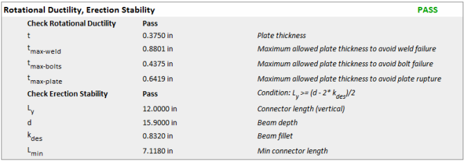
In order to ensure adequate rotational ductility in a shear tab shear connection the following three conditions must be satisfied:
The plate's flexural yield capacity is a direct function of its thickness. If a plate is too thick then its flexural yield capacity can be greater than the other capacities listed above, resulting in a non-ductile failure due to flexure.
Each of the three conditions above checks the maximum thickness based on AISC 360-10 (14th edition) eqn (10-3):
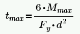
The calculation of Mmax is as follows:

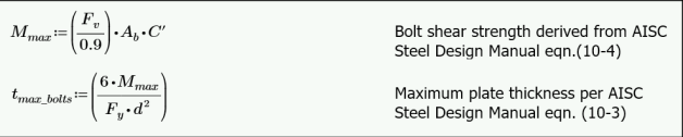
For reference see AISC 14th Edition Manual, Pages 9-14 and 10-104.
No rotational ductility checks are done for single angle connections. The AISC manual gives no guidelines on criteria, and these connections are typically considered to be sufficiently ductile regardless of configuration.
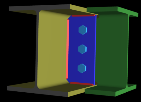
In the Shear Tab Connection module, when bolts are located between two horizontal welds, the connection lacks sufficient rotational ductility to be considered a proper shear connection. Therefore, the program will automatically fail such configurations under geometry restrictions due to inadequate rotational ductility as shown below.
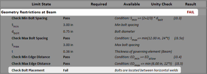
In these checks the program will check bolt spacing and edge distances against code prescribed minimums and maximums. These are checked for each element that is bolted in the program. Thus, this check will be given for each bolted element in a connection. When we do these checks we do them for both the member and the connector. We will check the worst case between the member and the connector.
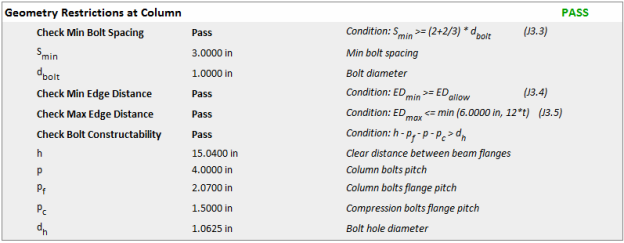
Section J3.3 of the AISC 360-10 specification gives a minimum spacing of 2 2/3*d. Thus, we will check both vertical and horizontal spacing of bolts against this minimum.
Section J3.5 of the AISC 360-10 specification gives a maximum spacing requirement for bolts. The program considers the members in the connection NOT subject to corrosion, thus uses a maximum distance of 24*thickness of thinner plate or 12 inches. J3.5(b) is not considered within the program. The program will check for the maximum edge distance in two orthogonal directions: the direction along the axial load in the connection, and the direction perpendicular to that.
Section J3.4 of the AISC 360-10 specification gives minimum edge distance requirements. This provision considers both Table J3.4 and J3.5, depending on the type of hole. Thus, the program combines the values from both Table J3.4 and J3.5 for checking minimum edge distance.
Regarding sheared edges versus rolled edges, the program makes this assumption:
Note that this check will only give detailed information if the minimum edge distance requirement was not met.
Section J3.5 of the AISC 360-10 specification gives a maximum edge distance of 12*thickness of connected part not to exceed 6 inches. Note that this check will only give detailed information if the maximum edge distance requirement was not met.
This check is applicable to all End Plate Moment connections. This common sense check ensures that the interior bolts do not overlap by limiting their spacing by a distance equal to the bolt hole dimension.
The program does not do any checks for Entering and Tightening Clearances per Tables 7-15 and 7-16 of the AISC 14th Edition Manual. Thus, you will have to verify these dimensions manually.
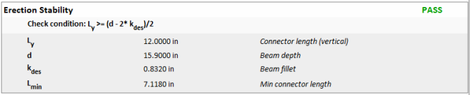
The AISC 14th edition steel manual introduced a new stability check for extended shear tab connections to determine if the shear tab needs to be stabilized or not.
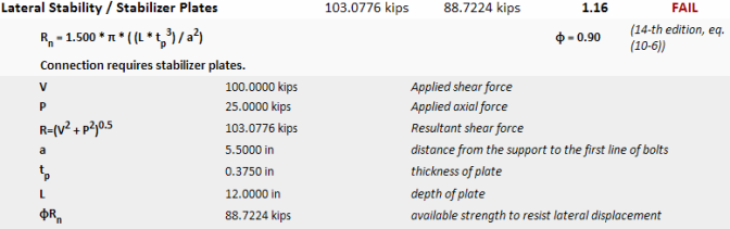
If this check fails there are different ways to resolve it: